
Top Benefits of Using Thermal Cameras for PCB Repair
As electronic products become increasingly multifunctional, circuit systems are evolving toward higher integration, smaller component packaging, and greater power density. The electronics industry is entering an era where high precision and high thermal loads coexist.
However, with higher integration comes a new set of challenges —thermal management and fault diagnosis. When the heat generated by electronic components during operation is not properly monitored or dissipated, it can compromise the performance, stability, and reliability of the circuit board, and may even lead to component failure during development or in actual use.
In high-density circuit boards, differences in current, voltage, and manufacturing processes result indistinct thermal distribution patterns across components. By accurately measuring and analyzing the board’s thermal profile, engineers can identify potential design weaknesses, optimize layout and cooling strategies, and ultimately improve product development success rates and long-term reliability.
Traditional contact-based temperature measurement methods are labor-intensive, intrusive, and slow to respond, making them unsuitable for modern high-density electronics. In contrast, infrared thermography—with its non-contact operation, real-time visualization, and high thermal sensitivity—enables precise quantification of temperature distribution and rapid detection of abnormal heat sources. It has therefore become an indispensable tool in electronic R&D, quality control, and fault analysis.
This article provides a systematic overview of infrared thermography in PCB testing and fault diagnosis, including its working principles, key advantages, typical application scenarios, and recommended product solutions, offering an efficient and data-driven approach to thermal design and reliability optimization in the electronics manufacturing industry.
1. Principles of Thermal Imaging and PCB Applications
1)Basic Principles of Infrared Thermal Imaging
All objects with a temperature above absolute zero (-273.15°C) emit energy in the form of infrared radiation. Infrared thermal cameras detect these radiation signals, convert them into electronic signals, and process them to generate a temperature distribution image. Different temperature regions are displayed in different colors, with high-temperature areas usually shown in red or yellow and low-temperature areas in blue or green.
2)Application Principles of Thermal Imaging in PCBs
When current flows through electronic components, it generates heat. Under normal operating conditions, the temperature distribution is stable and consistent with the expected power consumption. However, when faults such as short circuits, open circuits, cold solder joints, leakage, or aging occur, the local temperature distribution becomes abnormal. Thermal cameras can capture these changes and quickly and intuitively identify potential fault locations.
Unlike contact-based tools such as multi meters or oscilloscopes, thermal imaging does not require electrical connections or component disassembly, enabling comprehensive inspection of high-density, multi-layer PCBs.
2. Typical Application Scenarios
1)PCB Development and Temperature Monitoring
During the design and validation phase of a PCB, R&D engineers often need to monitor the temperatures of various electronic components under simulated real-world operating conditions. By recording the entire process from power-up to thermal stabilization, engineers can clearly understand the thermal distribution characteristics under different load conditions.
Infrared thermal cameras enable comprehensive, real-time temperature imaging of the PCB, helping engineers generate temperature distribution maps and variation curves for critical areas. Based on this data, components exhibiting overheating, uneven heat dissipation, or potential failure risks can be accurately identified, allowing engineers to adjust circuit layouts and optimize thermal management designs.

2)PCB Fault Localization and Maintenance
The PCB acts as the“nerve center” of an electronic system, and its reliability directly affects the overall performance of the device. Due to prolonged operation, external interference, or component aging, circuit boards may experience faults such as short circuits, cold solder joints, or breakdowns.
Traditional contact-based temperature measurement methods, such as thermocouple probes, are inefficient, provide scattered data, and are prone to missed detections. In contrast, infrared thermal cameras can capture the entire board’s temperature distribution in a single scan, enabling rapid identification of abnormally hot regions.
When internal shorts occur in chips, capacitors fail, or solder joints have poor contact, these faults manifest as localized abnormal heat patterns, which appear as distinct temperature anomalies in thermal images. Engineers can compare the thermal maps of normal and faulty boards to precisely locate the problematic components.
This approach significantly reduces the time required for traditional point-by-point measurements, making maintenance more efficient and reliable, particularly for complex circuits such as those in servers, communication base stations, and industrial control systems.

3)Chip Micro-Inspection and Non-Destructive Testing
As the core component of a PCB, a chip’s packaging quality and thermal performance are critical to the product’s lifetime and overall performance. During production and packaging, common defects include insufficient silver paste curing, solder joint contamination, and uneven stress on the chip frame, all of which can increase contact resistance and generate abnormal heat.
Microscopic infrared thermal cameras offer high spatial resolution and high sensitivity, enabling precise temperature measurement and imaging without physically contacting the chip surface. By capturing the real-time temperature distribution on the chip, engineers can quickly identify hotspots, and assess potential packaging process or material issues.


4)Thermal Design and Heat Optimization
As the performance of electronic devices continues to improve, the power consumption of chips and power modules is steadily increasing, making thermal design a critical factor affecting system stability and lifespan.
Thermal imaging cameras enable engineers to visually evaluate heat source distribution, thermal conductivity of materials, and the efficiency of cooling structures during the design phase. By monitoring real-time temperatures under different load conditions, engineers can assess whether heatsinks, thermal pads, and airflow channels are functioning effectively, and identify issues such as thermal accumulation or uneven heat transfer.
During R&D, engineers can adjust cooling paths and component layout based on thermal imaging results, thereby reducing the risk of thermal runaway and improving system reliability and energy efficiency. For high-performance computing devices, power inverters, and electric vehicle control modules, thermal imaging has become a standard tool for optimizing heat dissipation design.

5)Environmental and Dynamic Testing
During the design verification and reliability testing of electronic products, researchers often need to evaluate the dynamic thermal response of circuits under extreme temperatures, high currents, or complex electromagnetic environments.
Infrared thermal cameras can perform real-time dynamic temperature measurements under these extreme conditions, accurately capturing the entire temperature rise process of circuit components. For example, during probe station testing, as the current gradually increases, the thermal camera can simultaneously record the temperature curves of the probes and contact points, preventing measurement errors or component damage caused by overheating.

6)PCB Thermal Distribution Analysis
The thermal distribution of a circuit board directly affects its electrical performance, signal integrity, and product lifespan. Using infrared thermal imaging technology, engineers can generate high-resolution temperature distribution maps, providing a comprehensive view of the thermal characteristics across all areas of the PCB.
Thermal map analysis not only helps identify potential hotspots and localized thermal risks, but also enables the evaluation of the effectiveness of different cooling designs, material selections, or component layouts.

7)Semiconductor Equipment Temperature Monitoring
Infrared thermal cameras can provide real-time monitoring and early warning of overheating in semiconductor manufacturing equipment.
By implementing continuous thermal monitoring on high-value equipment such as lithography machines and ion implanters, abnormal temperature rises in critical components, including motors and bearings, can be detected in advance. This helps prevent equipment downtime due to overheating and reduces production losses.
In addition, the non-contact temperature measurement capability of infrared cameras effectively avoids direct contact between personnel and high-temperature components, significantly reducing safety risks while also enhancing automation and operational efficiency in the production process.


8)Power Distribution Cabinet Temperature Monitoring
The interior of power distribution cabinets contains densely packed equipment and complex electromagnetic environments. Over prolonged operation, components such as cables, busbar connections, and switch contacts are prone to increased local resistance due to poor contact, material aging, or mechanical wear, which can result in overheating, creating potential fire hazards and equipment failure risks.
Traditional temperature sensor methods face challenges including complicated installation, delayed response, unclear temperature distribution, and difficult maintenance, making comprehensive monitoring of complex cabinet interiors difficult.
For high-voltage switch gear with complex structures and limited space, infrared thermal cameras offer lightweight and convenient card-type monitoring solutions, enabling real-time internal temperature monitoring, automatic fault diagnosis, and anomaly alerts. Thermal imaging allows engineers to visually detect temperature distribution differences, identify potential hotspots in a timely manner, and significantly enhance the safety and reliability of cabinet operation.
Furthermore, the system can be paired with scenario-specific software platforms, including a lightweight real-time monitoring client and an integrated media cloud platform, supporting online video inspections, centralized management, and remote alerts, providing a comprehensive infrared thermal imaging solution for intelligent operation and safety monitoring of power distribution cabinets.
3. Recommended Products


4. Technical and Software Advantages
· Non-Contact and Safe:Temperature measurement can be performed without powering down or physically contacting the circuit, avoiding short circuits and secondary damage, particularly suitable for high-voltage or high-power systems.
· Visualized Temperature Distribution: Infrared thermal cameras generate intuitive temperature maps, allowing engineers to quickly identify hotspots. The accompanying software supports temperature curve display, hotspot tracking, and threshold-based alarms.
· High Sensitivity and Accuracy: Capable of detecting temperature differences as small as 0.02°C, making it especially effective for localized abnormal detection in high-density BGA and QFN packages.
· Rapid Fault Component Localization: The entire PCB can be scanned within seconds, quickly pinpointing areas of abnormal heat, significantly improving R&D and maintenance efficiency.
· Powerful Thermal Analysis Functions: Supports point, line, and area measurements, automatically generates temperature distribution maps and time-series curves, and produces standardized inspection reports to provide data for design verification and quality traceability.
· High-Definition Imaging and Data Management: Enables real-time imaging, video recording, and temperature curve analysis, facilitating comparison, archiving, and documentation.
· High-Sensitivity Temperature Detection: Features extremely responsive thermal sensing, precisely capturing minor heat variations and identifying potential risks.
· Intelligent Measurement Software: Supports multi-point measurement, area analysis, maximum/minimum temperature tracking, and alarm threshold settings, meeting the needs of research, production, and engineering applications.
5. Application Cases
Case 1: PCB Temperature Measurement Project for an Electronics R&D Company
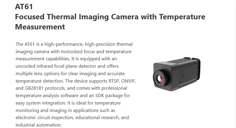
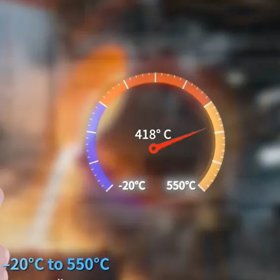
In this project, an online electro-optical temperature measurement infrared camera (ART61) was used to perform non-contact temperature monitoring of PCBs within a temperature-controlled chamber. The device features high sensitivity and a wide dynamic temperature response range, allowing it to accurately detect small temperature differences between components on the PCB even under ambient temperatures up to 60°C.
Case 2: LED Chip Production Inspection
During the production and packaging of LED chips, the process complexity and high precision requirements often lead to issues such as insufficient silver paste curing, electrode contamination, or misaligned solder joints. These defects can cause abnormal contact resistance, resulting in localized temperature rise, reduced luminous efficiency, or even chip failure.
By introducing theTN460 infrared thermal camera paired with the TI Studio professional thermal analysis software, engineers can perform non-contact, high-precision temperature measurement and thermal imaging of chips in macro/micro inspection mode. The system can display real-time temperature distribution differences for each chip and automatically identify abnormal hotspots, visually reflecting process deviations.
With software features such as multi-point measurement, temperature curve tracking, and automatic alarms, engineers can quickly pinpoint the root causes of process defects, such as uneven curing temperature or conductive layer contamination.
Conclusion
With the rapid development of electronic products and the increasing demand for thermal management, infrared thermal imaging technology has become a core tool for PCB design, inspection, and maintenance. It not only enables rapid fault localization and optimized thermal design, but also supports full-process thermal monitoring and visualized analysis.
Raythink will continue to focus on the infrared thermal imaging field, providing comprehensive solutions from R&D verification to production testing, helping the electronics industry move toward a more efficient and reliable future.
Recently Posted
-
International Day of Forests 2026: Safeguarding Forests and Economies with Thermal Imaging
April 24, 2026The theme of the International Day of Forests 2026, “Forests and Economies,” highlights the vital role forests play in supporting Read More
 -
Raythink Releases EV Lithium-ion Battery Thermal Safety White Paper
April 21, 2026As electric vehicles (EVs) continue their rapid global adoption, ensuring high-energy lithium-ion battery safety has become a crit Read More
 -
Application of Gas Detection Thermal Cameras in Environmental Monitoring
April 16, 2026In industrial production, energy transportation, cold chain operation and other scenarios, the leakage of VOCs (Volatile Organic C Read More
 -
Raythink’s AI-Powered Thermal Outdoor Security Cameras Protect Communities and Assets
April 14, 2026As winter conditions continue to impact parts of the United States and Europe, organizations are once again facing operational cha Read More

Contact Us
Recommended Products
-
 WN2 Imaging Thermal Module | Uncooled 12μm Infrared Camera Core With Multi-Resolution OptionsNegotiableMOQ: 1 Box
 -
640×512 High Resolution Uncooled Infrared OGI Camera RG630F for Petrochemical Gas SafetyUS$ 99999MOQ: 1 Set
-
RG630F AI Powered Handheld OGI Camera for Non-Contact Industrial Gas Leak Visual DetectionUS$ 99999MOQ: 1 Set
-
High-Sensitivity RG630C OGI Camera With Real-Time Gas Leak Monitoring & GPS TrackingNegotiableMOQ: 1 Set
-
Industrial-Grade RG630C OGI Camera for Oil, Gas and Petrochemical Leak MaintenanceNegotiableMOQ: 1 Set

-
AI-Powered RG630C Camera for Methane, Ammonia and SF6 Gas Leak VisualizationNegotiableMOQ: 1 Set
-
High-Resolution RG630C OGI Camera Compliant With EPA Appendix K for Gas Leak InspectionsNegotiableMOQ: 1 Set
-
RG630C Handheld OGI Camera for Non-Contact Visual Gas Leakage Detection & Safety MonitoringNegotiableMOQ: 1 Set
-
EX10 Infrared Thermal Imager for Precise HVAC Efficiency & Circuit Overheating ChecksNegotiableMOQ: 100 Sets
-
High-Performance EX10 Thermal Camera Enhancing Safety in Electrical MaintenanceNegotiableMOQ: 100 Sets
-
EX10 Thermal Imaging Device for Accurate Electrical & HVAC InspectionsNegotiableMOQ: 100 Sets
-
PC464A1 IP66 Rated Dual-Spectrum PTZ Camera With Thermal Imaging and 500m Surveillance RangeNegotiableMOQ: 100 Pieces
-
Raythink PC464A1 Dual-Spectrum PTZ Camera for Long-Range Perimeter Security and Fire DetectionNegotiableMOQ: 100 Pieces
-
PC464A1 Dual-Spectrum PTZ Camera With 30x Optical Zoom and AI Analytics for Critical Infrastructure SecurityNegotiableMOQ: 100 Pieces
-
High-Resolution 1280×1024 Uncooled VOx Infrared Thermal Imaging Module With LY300 ASICNegotiableMOQ: 1 Box
-
Long Wave Infrared Thermal Imaging Module TC 2-C With LY300 ASIC for Industrial MonitoringNegotiableMOQ: 1 Box
-
WN2 Series Uncooled Infrared Module With High-Frame-Rate 12μm WLP Detector for Intelligent Platform IntegrationNegotiableMOQ: 1 Box
-
RT630 Rugged Thermal Imaging Camera for Harsh Industrial Environments & Portable Electrical ChecksNegotiableMOQ: 50 Pieces
-
User-Friendly RT630 Thermal Camera With 8-Hour Battery & LCD Display for Field DiagnosticsNegotiableMOQ: 50 Pieces
-
Durable RT630 Thermal Imager With Enhanced Accuracy ±2°C/2% for Reliable Preventive MaintenanceNegotiableMOQ: 50 Pieces

